Stanton Tunnel
Now renamed RIDC Melton (Rail Innovation and Development Centre) the Old Dalby Test Track was originally built as the twin-track Nottingham and Melton Mowbray Railway which enabled express trains from London to the North to bypass Leicester and avoid a turnback at Nottingham. It opened 1879 and was closed in 1968. However, British Rail retained the line from Melton Mowbray to Edwalton as a test track, which is still in use to today.
One track runs for 13 miles between Melton Mowbray and Edwalton, has been electrified and is cleared for 125mph running. The other track, from Old Dalby to the entrance to Stanton tunnel, is just four miles long, and has London Underground-style four-rail DC electrification.
Stanton Tunnel
 At 1332 yards (1218m) Stanton tunnel is the longest of the four tunnels on the Nottingham to Melton Mowbray Railway. The others are Grimston tunnel (1305 yards, 1193m), Saxelby tunnel (543 yards, 497m) and Asfordby tunnel (419 yards, 383m). Construction of the line started in 1874, Stanton tunnel was completed in 1878 and the line was opened in 1879.
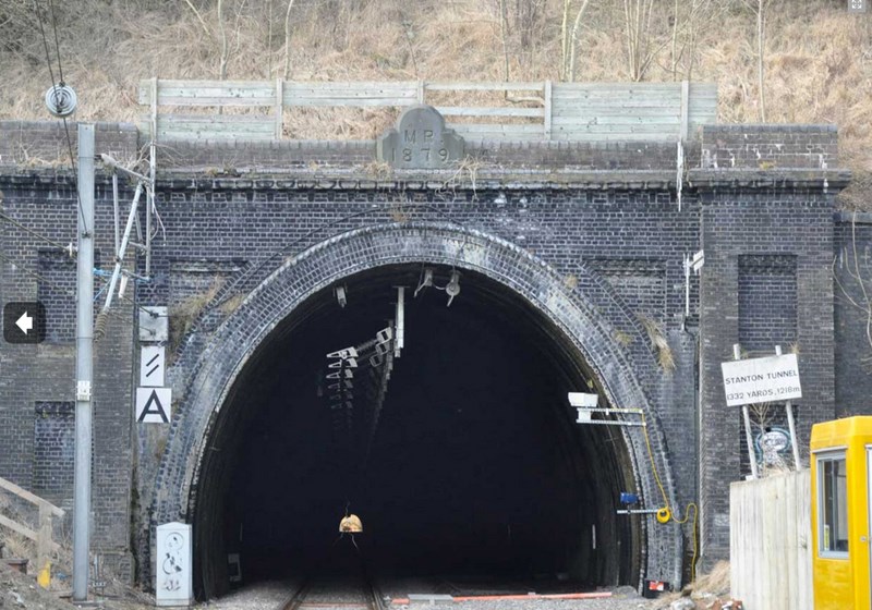
The South entrance to Stanton tunnel. The commemorative stone above the arch bears the legend "MR. 1879", signifying that it was constructed by the Midland Railway Company.
Projecting down from the tunnel roof can be seen the Furrer & Frey Rigid Overhead Conductor-rail System (ROCS) which supplies power via a rigid bar rather than a tensioned overhead line.
Tunnel Construction
 It's often thought that tunnels were constructed by starting at one end and burrowing through the hill to come out at the far side, or by starting at both ends and hoping to meet in the middle. However, in reality, excavation was carried out simultaneously at several points along the proposed line of the tunnel. This was achieved by sinking construction shafts from the surface down to the required depth.
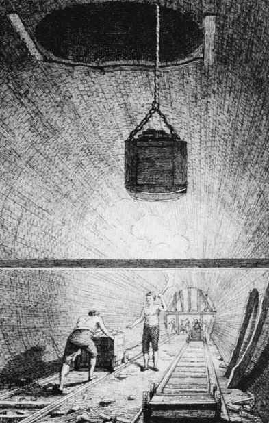
A stationery engine was used to haul baskets/tubs up and down the shaft between the tunnel floor and the surface. These were used to bring spoil up to the surface and to lower materials and equipment into the tunnel. They were also used to ferry the workmen (known as 'navvies') to and from the tunnel.
Once the navvies reached the bottom of the shaft, they would excavate 'pilot headings' seven or eight feet square in both directions towards the other shafts. Teams of navvies worked by candlelight in twelve-hour shifts.
A mariner's compass was used to indicate the direction of the excavation to the next shaft. When individual sections were eventually joined up they were often only a few inches out of alignment. Also there would be a noticeable improvement in both ventilation and drainage.
Once all the shafts had been joined up, plumb bobs were suspended from each shaft down to the proposed track level. Any motion of the weights due to air movement was damped by placing them in tubs of water.
The alignment of the plumb bob strings, and thus of the tunnel was then checked by siting them by eye and candle light. Once the alignment was agreed, the pilot headings were opened out to the full tunnel dimensions; it was only after this stage that the actual tunnel lining was put in place.
Tipping Wagons
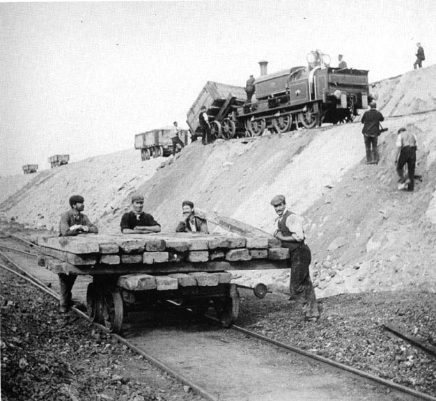 At the surface, spoil from the tunnel excavation would be put into tipping trucks propelled by a small steam engine running along a temporary rail-line to a suitable location to empty their contents.
Temporary rail tracks were used to move huge quantities of bricks, lime, cement, timber, spoil and ballast as well as the iron rails. The volume of spoil alone from the tunnel and shafts totalled approximately 20,000 cubic yards.
Tipping on the Great Central Railway in the 1890s. The locomotive pushing the tip wagons is a well-maintained 0-6-0 tank engine.
Taken from Chapter 7 of the book 'Navvyman' by Dick Sullivan which is available online here.
Ventilation Shafts
 Following completion of the tunnel some of the construction shafts were retained and lined with bricks to act as ventilation shafts to allow fresh air into the tunnel and the smoke from steam engines to escape. The remaining shafts were filled in.
Stanton tunnel has three brick-lined ventilation shafts; one is to the south of Browns Lane (and is the least accessible); the other two are visible from the path that runs along the route of the tunnel north of Browns Lane behind the houses fronting Melton Road.
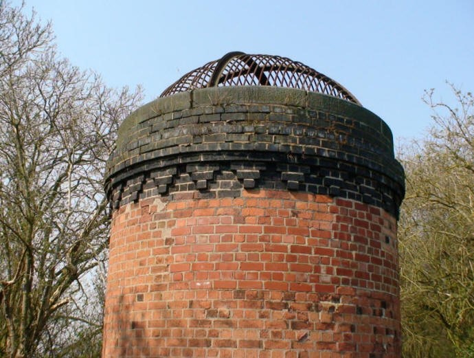
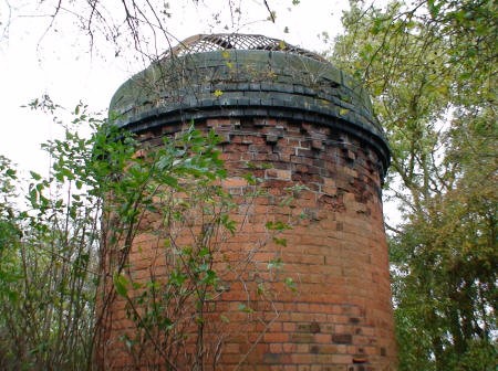
The most northerly of the three ventilation shafts along the Stanton Tunnel.
Note the protective metal cage over the top to prevent things being thrown into the tunnel. Remnants of earlier metal cages can still be found discarded on the sides of the spoil heaps at the shafts at both ends of the tunnel.
It isn’t known if any other construction shafts were sunk and were subsequently filled in, but this seems highly likely. The distance from the north portal of the tunnel to the first ventilation shaft is 850 feet (259m); it is 1060 feet (323m) to the second ventilation shaft; 1060 feet (323m) between the second shaft and the third shaft followed by a further 850 feet (259m) to the southern tunnel portal. This implies that there must be at least two (and possibly four) further filled in shafts.
The original plans show that the maximum depth of the shafts occurs at the central shaft nearest to Browns Lane, 79 feet from tunnel floor to the field level. Thus Stanton Tunnel is a relatively shallow one; indeed a previous owner of "Railway Cottage" (which is built along the line of the tunnel) is quoted as saying that "on frosty nights the [door] knobs in the cottage would rattle when express trains passed beneath".
Bricks
Bricks for lining Stanton tunnel and its ventilation shafts were almost certainly made on site, and it has been estimated that 12 million of them were required. The location of the brickworks is unknown but the spate of house building after the turn of the 20th century has probably obliterated all traces of them.
The ventilation shafts have 41 courses of common bricks visible above the surface of the ground, followed by 7 courses of blue engineering bricks, topped by a ring of curved dressed masonry coping stones.
On the northernmost ventilation shaft, some bricks on the outer course appear to have weathered badly. A section half way up the stack has been replaced by modern bricks bearing the maker’s name. The original bricks are still scattered around on the slopes of the spoil heap and bear no identification marks — which would be expected if they were made on site. The original bricks measure 8¾ x 4½ x 3 inches.
 The middle shaft brickwork and masonry looks to be in quite good condition. However the ventilation shaft at the south end of the tunnel is in a relatively bad state.
The most southerly of the three ventilation shafts along the Stanton Tunnel.
There are patches of exploded bricks where damp and frost has penetrated. Hawthorn is growing around the masonry top, forcing the blocks apart in several places.
Strong galvanised wire has been looped around the top rows of bricks to hold them in place.
Ventilation Shafts Revisited
 During the era of steam and diesel hauled trains, the ventilation shafts were necessary to allow fresh air into the tunnel and smoke/diesel fumes out. However electric trains have no need of ventilation shafts, so new tunnels are constructed without them
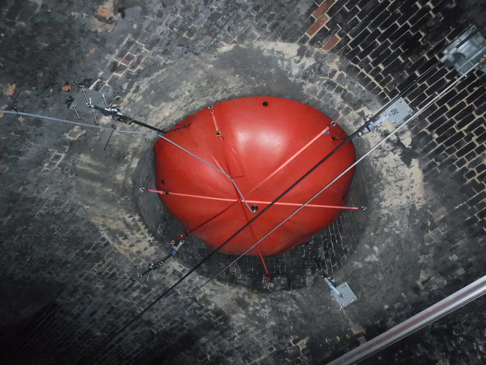
This presents a problem for the test track – how to use a tunnel that does have ventilation shafts to simulate the behaviour of a train in a tunnel that doesn’t have ventilation shafts. In March 2017, this problem was solved by temporarily installing balloons at the bottom of the three ventilation shafts, thus effectively blocking them off.
A fully-inflated balloon is used to seal off Stanton tunnel’s ventilation shafts to simulate aerodynamic and pressure pulse testing in a tunnel that didn’t have any ventilation shafts.
Read the full story on the Rail Engineer.
Stanton on the Wolds Parish Council would like to thank Alan and Val Hunt of Melton Road for their original article and research on which this page is based. This information given here, in regard to the ventilation shafts in partuicular, was correct when the original article was compiled.